
Aristotle University Racing Team Electric and Driverless (Aristurtle) is a Greek student research team at Aristotle University of Thessaloniki that designs and builds electric and driverless race cars. It was established in 2013 and primarily competes in international Formula Student competitions, which focus on the design, engineering, and performance of race cars. The team is multidisciplinary, involving students from fields like electrical, mechanical, and computer engineering.
This GitHub Gist presents my contribution to the Aristurtle as an Embedded System Designer for the 2020-2021 season. More precisely, I was a member of the driverless sub-team, whose primary goal was to convert the previous season's electric vehicle, named "Thetis," into Greece's first autonomous racing car, known as "Thetis DV."
An important note is that while I can't provide any of the source code of any of the projects, I am more than happy to discuss the general approach and offer guidance on similar problems.
- Thetis DV Overview
- Custom ECU
- Other Electronics Projects
- Other Software Projects
- Competition and Media

Racing cars, like other high-performance vehicles, incorporate numerous microcontrollers strategically placed throughout the vehicle. These sophisticated devices are responsible for critical functions such as sensor data acquisition and the control of various components, including electric motors, cooling system water pumps, and the dashboard interface. Our team custom-designed these microcontrollers to meet the specific demands of our racing car. The following table outlines these microcontrollers and highlights some of their key features.
| sTurtle | TMsTurtle | Aristuino |
|---|---|---|
 |
 |
 |
| STM32F446RE | TMS320F28379S | ATMEGA2560-16AU |
| 180 MHz 32-bit Cortex M4 | 200MHz 32-bit C28x CPU | 8-bit AVR |
| DSP instructions, low power modes, rich peripherals | Specialized for real-time control and digital signal processing | Low power consumption, extensive I/O capabilities |
The diagram below illustrates the distribution of smart devices within our vehicle and their data exchange pathways. Three primary communication protocols are employed:
- Controller Area Network (CAN) bus: This standard protocol utilizes a broadcast-based, message-oriented approach. CAN ensures data integrity, prioritization, and reliability through differential signaling, effectively mitigating electrical noise in the harsh racing environment.
- Serial Peripheral Interface (SPI): This protocol adheres to a master-slave architecture. A primary device orchestrates communication with one or more subordinate (peripheral) devices by managing clock and chip select signals. SPI's key advantage is its high data transfer rate, though this comes at the cost of requiring shorter connection cables.
- Serial Communication: This simple and versatile protocol transmits data sequentially, one bit at a time. It supports both synchronous and asynchronous transmission, making it suitable for a wide range of applications. While generally slower than SPI, serial communication excels in scenarios requiring longer-distance data transmission and simpler wiring.
These communication systems work in tandem to create a robust, efficient network of smart devices that optimize our vehicle's performance and reliability. Each protocol is chosen based on the specific requirements of the devices it connects, balancing factors such as speed, distance, and complexity of implementation.

| Device | uController/ Manufacturer | Usage description |
|---|---|---|
| AMI (Autonomous Mission Indicator) | sTurtle | Responsible for accepting a user input autonomous mission and displaying it on the dashboard. |
| AMS (Accumulator Management System) | Aristuino | Monitors all the BMS slave devices. |
| APU (Autonomous Processing Unit) | Sincoze | A x64 computer empowered with a neural network for autonomous driving. |
| AUX (Auxiliary Unit) | sTurtle | Responsible for interfacing with the vehicle's rear sensors and devices. |
| BMS (Battery Management System) | LTC6803 | Monitors voltage of battery cells and reports to AMS. |
| Dashboard | sTurtle | Responsible for acquiring the data of the vehicle's front-side sensors and displaying information on the driver's dashboard. |
| EBS (Emergency Brake System) | sTurtle | During an emergency, it triggers a hydraulic system that activates the brakes. |
| ECU (Electronics Control Unit) | TMsTurtles | Controls the vehicle's motors, checks for errors, coordinates the rest devices, etc. |
| INS (Inertial Navigation System) | SBG Systems | Provides navigation and heading for the vehicle. |
| Inverter (Left, Right) | Unitek | Power inverters for supplying and controlling the vehicle's motors. |
| Isabellen | Isabellenhütte | High voltage and current measurement sensor. |
| RES (Remote Emergency System) | Gross Funk | A device that allows remote braking of the vehicle during an emergency. |
| Steering | sTurtle | Controls the stepper motor that turns the steering wheel. |
As a member of the Aristurtle team, my primary focus was on the design and implementation of the vehicle's Electronic Control Unit (ECU). This critical component serves as the brain of our racing car, performing several vital functions:
- Safety Assurance: The ECU conducts comprehensive pre-drive checks and continuous monitoring during operation, ensuring optimal safety conditions.
- Power Management: It calculates and applies the appropriate torque output by:
- Implementing sophisticated power limitation policies
- Managing regenerative braking systems
- Controlling the electronic differential for improved handling and performance
- Peripheral System Control: The ECU oversees various auxiliary vehicle systems, including:
- Thermal management through the cooling system
- Driver communication and safety features via light indicators
Using Altium Designer, I engineered a Printed Circuit Board (PCB) to house the microcontrollers and essential peripheral circuitry, ensuring the optimal functionality of the ECU. The hardware architecture of the ECU comprises:
- Dual Processing Core:
- Two TMsTurtle microcontrollers execute complex algorithms
- Inter-processor communication via high-speed serial interface
- Robust Communication Infrastructure:
- Four isolated CAN channels facilitate reliable data exchange with various vehicle components
- Advanced Signal Processing:
- Four dedicated Analog-to-Digital Converters (ADCs)
- Four versatile circuits, configurable as ADCs, Digital-to-Analog Converters (DACs), or voltage dividers
- All analog circuits feature buffer stages for signal integrity.
- Comprehensive I/O Management:
- Six digital output channels
- Two digital input channels
- Integrated logic level converters supporting 3.3V, 5V, and 24V standards for seamless interfacing with diverse components

 |
 |
|---|
The ECU's core processing power consisted of two TMsTurtle microcontrollers, developed in-house by our team. Although their processors, manufactured by Texas Instruments (TI), are typically programmed using TI's Code Composer Studio (CCS), for our application, we decided to utilize MATLAB Simulink from MathWorks as our primary development environment. This choice was a result of several compelling factors:
- Rapid Prototyping and Simulation: Simulink provides a comprehensive simulation environment, enabling quick algorithm design, testing, and validation before deployment on hardware.
- Model-Based Design: Simulink's graphical programming interface allows the creation of complex control systems, facilitating easier collaboration among team members with diverse expertise.
- Automatic Code Generation: Simulink can automatically generate C code from block diagrams, reducing manual coding errors and accelerating process development.
- Extensive Toolbox Library: Simulink has access to pre-built and optimized functions for control systems, signal processing, and other domains relevant to automotive applications.
- Hardware-in-the-Loop (HIL) Testing: Simulink supports HIL testing, allowing for real-time validation of control algorithms with actual hardware components.
As mentioned, the ECU's functionality was distributed across two specialized microcontrollers: the Front End and Back End, each with distinct yet complementary responsibilities.
The Back End microcontroller served the role of the powertrain management unit, focusing on motor control and torque optimization. Its primary functions included torque calculation and control, processing desired torque inputs from the autonomous system, implementing power control limitations (both user-defined and hardware-specific), managing regenerative braking for energy efficiency, and executing electronic differential algorithms for improved vehicle dynamics. Additionally, it handled inverter communication, translating calculated torque values into appropriate commands for the motor inverters.
The Front End microcontroller acted as the vehicle's sensory and auxiliary control hub. Its key responsibilities encompassed data acquisition and processing from the vehicle's sensors. It performed continuous safety checks based on real-time sensor data and implemented fail-safe protocols when necessary. The Front End also managed auxiliary systems, controlling critical components such as light indicators (including brake lights) and Autonomous System Status Indicators (ASSIs). Furthermore, it oversaw the thermal management systems for inverters, motors, and the accumulator.
Both microcontrollers utilized a sophisticated software architecture designed for optimal performance and safety. This architecture leveraged hardware timers for precise task scheduling, enabling real-time processing. An interrupt-driven design was implemented with a hierarchical structure, prioritizing critical safety-related data paths for immediate execution and ensuring lower-priority tasks did not interfere with essential vehicle operations. The software design also focused on resource optimization, balancing the computational load between microcontrollers for efficient processing.
| Front End Model | Back End Model |
|---|---|
 |
 |
We developed a Simulink-based dashboard to facilitate efficient debugging and parameter optimization of the ECU. This powerful interface offered dual connectivity options for enhanced flexibility in development and testing scenarios.
The primary method employed a direct wired connection, linking the ECU's two microcontrollers to the host computer via serial communication. This approach provided low-latency, high-fidelity data transfer for intensive debugging sessions and real-time parameter adjustments.
Alternatively, we implemented a wireless solution to enable remote diagnostics and tuning. With this configuration, the APU served as an intermediary, hosting a custom service application. This application acted as a bridge, seamlessly converting serial messages from the ECU into Robotic Operating System (ROS2) messages. By leveraging the ROS2 ecosystem, we created a robust, scalable communication framework.This wireless setup allowed any authorized host computer to interface with the ECU remotely provided the computer and the APU were on the same network. This capability proved invaluable for field testing, enabling real-time adjustments and diagnostics without physical access to the vehicle's systems.
 |
 |
|---|---|
 |
 |
The ECU was housed in a custom-designed dual-compartment enclosure, using SolidWorks CAD from Dassault Systèmes, to ensure optimal performance and protection in the demanding racing environment. This enclosure was fabricated using 3D printing techniques with high-grade ABS (Acrylonitrile Butadiene Styrene) material, chosen for its excellent balance of strength, heat resistance, and electrical insulation properties.
The enclosure's dual-compartment design served a crucial purpose beyond physical protection. The surface between the compartments was lined with precision-applied copper mesh, creating a Faraday cage effect. This copper mesh had direct contact with the vehicle's chassis, establishing a continuous conductive path.
The integration of copper mesh served two critical functions:
- Galvanic Isolation: By creating a conductive barrier between the ECU's sensitive electronics and the external environment, the design mitigated the risk of ground loops and potential differences that could arise from the vehicle's complex electrical systems.
- Electromagnetic Interference (EMI) Suppression: The copper mesh effectively formed an electromagnetic shield, significantly attenuating external EMI that could disrupt the ECU's operations. Simultaneously, it contained any electromagnetic emissions from the ECU itself, preventing interference with other onboard electronic systems.

The Autonomous Mission Indicator (AMI) project was developed to fulfill the requirements for driverless vehicles in Formula Student competitions. The AMI allows team members to select and indicate the current autonomous mission for the car. The implementation uses a rotary switch for mission selection and a series of LEDs for mission indication. The AMI was integrated into the vehicle's dashboard for easy accessibility from inside and outside.
The PCB design for the AMI project was carefully crafted to fit within the Thetis dashboard. The brain of the circuit was a custom-made sTurtle board featuring an STM32F446RE microcontroller. The PCB incorporates a 7-position rotary switch for mission selection and seven blue LEDs for mission indication, both connected via Molex connectors for easy panel mounting. Power management was handled by two DC/DC converters: one converts 24V to either 5V or 3.3V for the microcontroller and switches, while another converts 24V to 12V for the LEDs. The board includes safety features such as fuses and indicator LEDs for power failure protection. To interface the 3.3V logic of the microcontroller with the 12V LEDs, the PCB employs a ULN2004ADR chip. The rotary switch circuit includes pull-up resistors for safety and RC filters to eliminate debouncing, ensuring reliable mission selection.
The software implementation for the AMI project focuses on robust mission detection and communication. The code utilizes timer interrupts to poll the rotary switch every 100ms, storing the detected mission in a circular memory array. This approach prevents rapid mission changes during switch rotation, only updating the selected mission when it remains stable for a set duration. The software communicates over CAN bus, transmitting the chosen mission and receiving updates from the APU. Error handling was implemented to detect communication timeouts with the APU, triggering a safe state if necessary. The code also manages LED indicators, updating them based on the current mission state.
 |
 |
 |
|---|
The Autonomous System Status Indicators (ASSI) project was developed to meet the requirements for driverless vehicles in Formula Student competitions. The project's goal was to create a system that indicates the status of the Autonomous System (AS) through illuminated indicators visible from all angles of the vehicle. The ASSI system consists of three indicators: two mounted on each side of the car behind the driver's compartment and one at the rear. These indicators use different illumination patterns (off, continuous yellow, flashing yellow, flashing blue, and continuous blue) to represent various AS states (AS Off, AS Ready, AS Driving, AS Emergency, and AS Finished, respectively).
The PCB design for the ASSI project was crafted to meet Formula Student competition requirements for driverless vehicles. Each PCB hosts blue and yellow LEDs to indicate the AS state. The board is powered by 24V from the Low Voltage Master Switch and controlled by 5V signals from the ECU. To efficiently drive multiple LEDs while minimizing current draw from the ECU, the design incorporates a SZNUD3160LT1G IC, which acts as a switch to control the 24V LED power using 5V logic signals. The PCB includes pull-down resistors to ensure all LEDs are off in case of an open wire. The PCB design also accounted for proper heat dissipation and adhered to the minimum illuminated surface area of 15 cm² as per competition rules.
The software implementation for the ASSI project was integrated into the existing ECU code, eliminating the need for a separate microcontroller. The software design focused on two main tasks: receiving the AS state via CAN messages from the Autonomous Processing Unit (APU) and controlling the ASSI LEDs based on this state. The code utilizes the ePWM2 timer to generate a 6Hz interrupt for LED toggling in specific AS states. A switch-case structure was implemented to handle different AS states, setting the appropriate LED states for each condition. The software also includes safeguards such as input validation and error checking to ensure reliable operation.
 |
 |
 |
|---|
This control board was primarily designed for system monitoring of the APU and its thermal management. At its core, the board translates digital signals from the APU into visible LED indicators, providing at-a-glance status information for up to eight different parameters or conditions. These parameters were user-defined, as a service application was running on the computer, listening for ROS2 messages. Complementing this visual feedback system, the board incorporates a fan speed control mechanism. By utilizing a 555 timer circuit in conjunction with a user-adjustable potentiometer, it generates a pulse-width modulated (PWM) signal dynamically regulating the APU's case cooling fan speed.
 |
 |
 |
|---|
Another project under my responsibility was the integration of the Inertial Navigation System (INS) from SBG Systems. This advanced sensor played a dual role, serving the autonomous driving system and the ECU for precise torque calculations. It interfaced with the APU via a high-speed serial connection, while simultaneously broadcasting critical data over the CAN bus for the ECU.
At the heart of this integration was a ROS2-based service running on the APU. This service was responsible for:
- Establishing and maintaining robust communication with the SBG device
- Dynamically configuring the INS based on parameterized ROS settings
- Processing and publishing a wide array of sensor data to various ROS topics
The service periodically handled multiple message types from the INS, including:
- System status information
- Precise UTC time synchronization
- High-frequency IMU data
- Extended Kalman Filter (EKF) outputs for navigation and orientation
- GPS data for global positioning
- Odometry information for local movement tracking
Where necessary, the service performed coordinate frame transformations to ensure consistency across the autonomous system. It then published this data in formats compatible with standard ROS message types, such as Odometry and TF (Transform) messages. This architecture enabled the self-driving algorithms to access high-fidelity, low-latency sensor data, critical for accurate vehicle state estimation, prediction, and control.
This project focused on developing a robust bridge between the autonomous system and the vehicle's native systems. We implemented a CAN interface using a Kvaser PCI card installed in the APU. The core of this solution was a ROS2-based service leveraging the SocketCAN library, providing a seamless integration layer between the autonomous driving stack and the vehicle's CAN network.
- System Initialization
- Configuration Management: Dynamically loads and applies configuration parameters from ROS2, allowing for flexible setup and easy adjustments.
- Dual-Channel CAN Interface: Initializes and manages two separate CAN channels, enabling communication with different vehicle subsystems.
- Timer-Based Operations: Implements precise timers for CAN message reception and transmission, ensuring consistent and timely data flow.
- ROS2 Integration: Sets up a comprehensive suite of ROS2 publishers and subscribers, facilitating seamless data exchange between the CAN network and the autonomous driving stack.
- CAN Message Reception
- Continuous Monitoring: Actively listens for incoming CAN messages on both channels, ensuring no critical vehicle data is missed.
- Message Decoding: Efficiently unpacks and interprets various CAN frame types, including AMI selected mission, vehicle RPM, EBS supervisor status, steering wheel angle, and more.
- Real-time Data Publishing: Converts decoded CAN data into ROS2 messages, making it immediately available for autonomous driving algorithms, vehicle telemetry and diagnostics, and data logging and analysis systems.
- CAN Message Transmission
- Message Encoding: Accurately packs ROS2 messages into standardized CAN frames, ensuring compatibility with vehicle systems.
- Critical Command Transmission: Periodically sends essential control commands, including EBS service brake commands, steering wheel angle instructions, and APU torque commands.
- Intelligent Data Conversion
- Raw Data Processing: Implements algorithms to convert raw sensor data into meaningful physical units.
- Calibration and Scaling: Applies vehicle-specific calibration factors and scaling to ensure accuracy across different sensor types and ranges.
- Unit Standardization: Ensures all data is converted to consistent units, facilitating easier integration with the autonomous driving stack.
- Robust Error Handling and Logging
- Comprehensive Error Detection: Implements thorough checks for issues in message unpacking, packing, and transmission processes.
- Detailed Error Logging: Provides granular error messages with specific error codes, timestamps, and contextual information.
- Graceful Degradation: Implements fallback mechanisms to maintain system stability in case of communication failures.
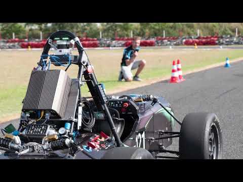
In July 2021, Thetis DV made its debut at the Formula Student EAST competition, held at Hungary's prestigious Hungaroring racetrack. The team's performance was remarkable, especially for a first-time entrant. Thetis DV's vehicle not only passed all technical inspections, including the rigorous autonomous system evaluation, but also successfully competed in every dynamic event: acceleration, autocross, trackdrive, and skidpad.
This comprehensive participation is a rare feat in Formula Student competitions, with only a select few teams historically managing to clear all inspections and complete all dynamic events in their inaugural appearance. Thetis DV's achievement becomes even more impressive considering the competition's high standards and the complexity of fielding an autonomous vehicle.
The team's efforts culminated in a podium finish, securing 3rd place in the skidpad event. This stellar performance, combined with strong showings in other events, propelled Thetis DV to an overall 4th place ranking in the dynamic events category, outperforming most of the field in a competition that featured over 12 participants.
| Thetis DV Reveal | FS Competitions 2021 Aftermovie |
|---|---|
 |
 |
| T.I.F. Helexpo 2021 | Interview from ERT |
 |
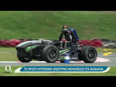 |