- ASUS G14 stores its UEFI (BIOS) settings in its 16MiB SPI Flash ROM (NVRAM region).
- The NVRAM region can be cleared by:
- Dumping the flash ROM contents with
flashprog(using an opensensor/pico-serprog or dword1511/stm32-vserprog flash programmer). - In the ROM dump, replacing the NVRAM region with the clean state from an EZFlash update file using
UEFIToolandUEFIToolNE. - Writing the modified NVRAM region back into the Flash ROM.
- Dumping the flash ROM contents with
I accidentally bricked my ASUS Zephyrus G14 GA401 (2021) Laptop while playing with Smokeless_UMAF, and it stuck on power-on even without the ROG Logo appearing. Since traditional "CMOS clear" methods (such as long-pressing the power button, cutting off the battery pack for a while, or pressing Ctrl + Home to launch EZFlash) didn't work for me, I had to dump the contents of the Flash ROM chip and write the modified contents back into the chip.
Thanks to open-source tools for handling SPI Flash ROM and UEFI files, I successfully unbricked my laptop. This is primarily a memo for myself. Attempting this procedure is at your own risk.
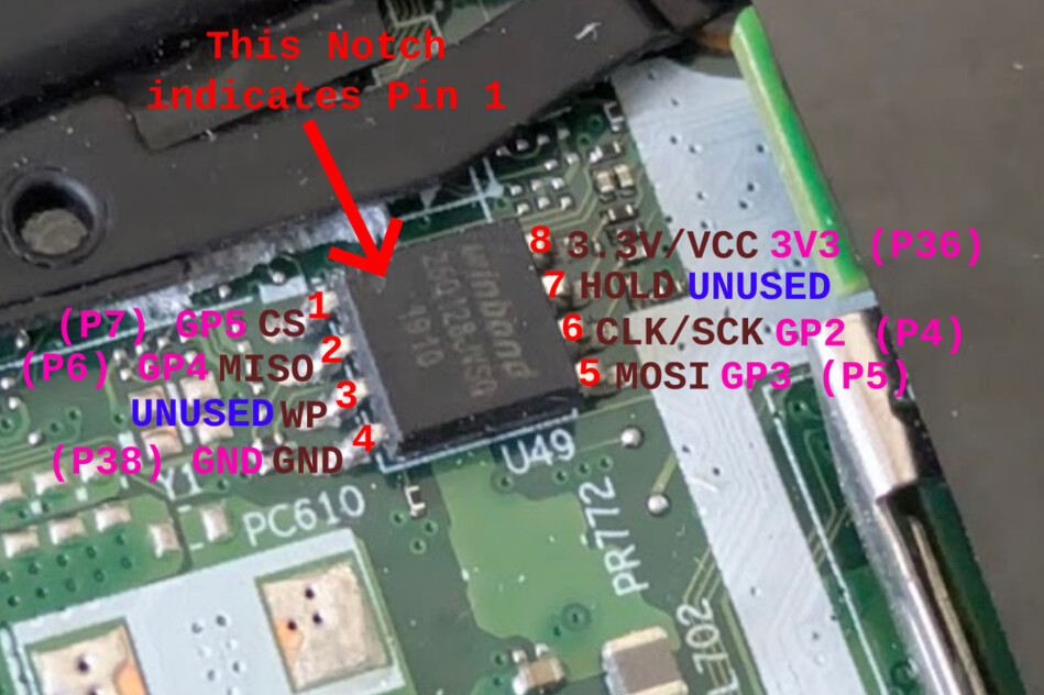
- On my laptop, the SPI Flash ROM (Winbond W74M12JWSIQ, 128Mbit, @1.8V) is located between the M.2 NVME socket and the battery.
- I directly soldered some wires onto the pins: CS, MISO, GND, MOSI, CLK, VCC.
- As a flash programmer, I tried the following, and both worked:
- An RP2040 RPi Pico with opensensor/pico-serprog firmware.
- An STM32F103 Blue Pill with dword1511/stm32-vserprog firmware.
- Also, I used a cheap 3.3V/1.8V level shifter found on my desk, but it turned out to cause read inconsistency (random bit rot), so I just put a 1k/1k voltage divider on CLK and connected MISO directly.
- These serprog-compatible programmers can be controlled by
flashromor its fork from the Libreboot team,flashprog.flashromcan be installed using apt-get, whileflashprogcannot. However,flashprogis seemingly more feature-rich (e.g., supports the--progressflag, etc.).- I used
flashprogvia anarchilinuxDocker container. - References:

The following is cited from the Libreboot docs. Note in this case VCC is 1.8V.
- Using an RP2040 RPi Pico with opensensor/pico-serprog firmware.
- The prebuilt binary can be found at Release v1.0.0 · opensensor/pico-serprog. Download the
.uf2file, power the board while pressing the BOOT button, then copy the file to theRPI-RP2drive. - The pinouts are:
- GP2: SCK
- GP3: MOSI
- GP4: MISO
- GP5: CS

- Using an STM32F103 Blue Pill with dword1511/stm32-vserprog firmware.
- No prebuilt binary is available, but a detailed guide can be found in the README.
- Put it in ISP mode by configuring the on-board jumpers as BOOT0=1 and BOOT1=0. Connect PA9 (TX) and PA10 (RX) to a USB Serial adapter. After flashing, make sure BOOT0=0.
- The pinouts are: (ref: Pull Request #7 · dword1511/stm32-vserprog)
- PA6: MISO
- PA7: MOSI
- PA4: CS
- PA5: SCK
$ git clone --recurse-submodules https://github.com/dword1511/stm32-vserprog.git
$ cd stm32-vserprog
$ git log | head -1
commit c74b4ed5704907f56e6ed1fa59d1874fd8de1bda

$ sudo apt-get install -y stm32flash gcc-arm-none-eabi

$ make BOARD=stm32-bluepill
$ sudo make BOARD=stm32-bluepill flash-uart
- First, dump the current Flash ROM contents.
# Start archilinux container. Here ttyACM1 is the flasher, identified from `ls -hl /dev/serial/by-id`
$ docker run --rm -it -v $PWD:/wd -w /wd --device /dev/ttyACM1 archlinux:latest bash

# Install flashprog
$ pacman -Sy flashprog
$ flashprog -V
flashprog v1.4-dirty on Linux 6.8.0-55-generic (x86_64)
flashprog is free software, get the source code at https://flashprog.org
...

# Read and determine the flash
$ flashprog --progress -p serprog:dev=/dev/ttyACM1,spispeed=2M -r g14-bios.flashprog.bin
flashprog v1.4-dirty on Linux 6.8.0-55-generic (x86_64)
flashprog is free software, get the source code at https://flashprog.org

Using clock_gettime for delay loops (clk_id: 1, resolution: 1ns).
serprog: Programmer name is "pico-serprog"
Warning: NAK to query operation buffer size
Found Winbond flash chip "W25Q128.W" (16384 kB, SPI) on serprog.
...
Reading... [==================================================] 100% done.

# Verify the dump
$ flashprog -V --progress -c W25Q128.W -p serprog:dev=/dev/ttyACM1,spispeed=2M -v g14-bios.flashprog.bin
...
Reading... [==================================================] 100% VERIFIED.- Obtain a BIOS update file (a zip archive for EZFlash) from the ASUS website.
$ unzip GA401QCAS415.zip
inflating: GA401QCAS.415- Download UEFITool NE binary.
- Download UEFI Tool binary.
- https://github.com/LongSoft/UEFITool/releases/tag/0.28.0
- UEFITool NE is a successor, but it does not support editing yet. Therefore, I used UEFITool NE for analyzing and extracting the NVRAM file, and then used UEFI Tool to modify the dump file.
- Open the BIOS update file with
UEFI Tool NE.- Expand
AMI Aptio capsule > UEFI image > AmiStandardDefaultsVariable > NVRAM. - Right click on
NVRAMandExtract as isto save.ffsfile. - Note the File GUID for NVRAM (e.g.
CEF5B9A3-...) 
- Expand
- Open the dump file with
UEFI Tool.- Expand
UEFI image > <First Volume UUID>. Right-click the file with the same UUID (matching the NVRAM File GUID noted earlier). - Right-click on
CEF5B9A3-(or the corresponding UUID) andReplace as is. Load the.ffsfile that you extracted from the BIOS update file. - Save the modified file by selecting
File > Save image file. (g14-bios.flashprog.replaced.bin) 
- Expand
- Now write the modified version to the ROM.
# Create a layout file to avoid full-flash.
# The content length is guessed from the layout from UEFITool NE.
$ vi flash.layout
$ cat flash.layout
00000000:0001ffff nvram
00020000:00ffffff other

# Write nvram region.
$ flashprog -V -c W25Q128.W --layout flash.layout --image nvram --progress -p serprog:dev=/dev/ttyACM1,spispeed=2M -w g14-bios.flashprog.replaced.bin
...
Using region: "nvram".
Reading old flash chip contents...
Reading... [==================================================] 100% done.
Erasing and writing flash chip...
Erasing... [==================================================] 100% , 0x010000-0x01ffff:E
0x000000-0x01ffff:
Writing... [==================================================] 100% W
Erase/write done.
Verifying flash...
Reading... [==================================================] 100% VERIFIED.- DONE. Remove the flasher and power the laptop. Fingers crossed.
The approach described here worked perfectly using CH341A SPI programmer on GA401IV that is using Macronix MX25U12835F flash memory in place of Winbond chip, despite Macronix chip being marked as untested in flashrom. Thank you for the guidance!
One point of caution is that on my motherboard there was another, much smaller (8 Mbit) Winbond flash memory chip that is not relevant here, but could be confused for the correct one.