You signed in with another tab or window. Reload to refresh your session.You signed out in another tab or window. Reload to refresh your session.You switched accounts on another tab or window. Reload to refresh your session.Dismiss alert
There is sometimes a confusion between integration tests and functional tests as they both require multiple components to interact with each other. The difference is that an integration test may simply verify that you can query the database while a functional test would expect to get a specific value from the database as defined by the product requirements.
Continuous Integration is a software development practice where members of a team integrate their work frequently, usually each person integrates at least daily - leading to multiple integrations per day. Each integration is verified by an automated build (including test) to detect integration errors as quickly as possible. Many teams find that this approach leads to significantly reduced integration problems and allows a team to develop cohesive software more rapidly. This article is a quick overview of Continuous Integration summarizing the technique and its current usage.
Continuous Delivery is a software development discipline where you build software in such a way that the software can be released to production at any time.
You’re doing continuous delivery when: [1]
Your software is deployable throughout its lifecycle
Your team prioritizes keeping the software deployable over working on new features
Anybody can get fast, automated feedback on the production readiness of their systems any time somebody makes a change to them
You can perform push-button deployments of any version of the software to any environment on demand
Development server acting as a sandbox where unit testing may be performed by the developer
Integration
CI build target, or for developer testing of side effects
Testing/Test/QC/Internal Acceptance
The environment where interface testing is performed. A quality control team ensures that the new code will not have any impact on the existing functionality and tests major functionalities of the system after deploying the new code in the test environment.
Summary: “Kanban vs. scrum” is a discussion about two different strategies for implementing an agile development or project management system. Kanban methodologies are continuous and more fluid, whereas scrum is based on short, structured work sprints.
Broadly speaking, there are at least three levels of testing: unit testing, integration testing, and system testing.[39][40][41][42] However, a fourth level, acceptance testing, may be included by developers. This may be in the form of operational acceptance testing or be simple end-user (beta) testing, testing to ensure the software meets functional expectations.[43][44][45] Based on the ISTQB Certified Test Foundation Level syllabus, test levels includes those four levels, and the fourth level is named acceptance testing.[46] Tests are frequently grouped into one of these levels by where they are added in the software development process, or by the level of specificity of the test.
Unit testing
Unit testing refers to tests that verify the functionality of a specific section of code, usually at the function level. In an object-oriented environment, this is usually at the class level, and the minimal unit tests include the constructors and destructors.[47]
Integration testing
Integration testing is any type of software testing that seeks to verify the interfaces between components against a software design. Software components may be integrated in an iterative way or all together ("big bang"). Normally the former is considered a better practice since it allows interface issues to be located more quickly and fixed.
System testing
System testing tests a completely integrated system to verify that the system meets its requirements.[6]: 74 For example, a system test might involve testing a login interface, then creating and editing an entry, plus sending or printing results, followed by summary processing or deletion (or archiving) of entries, then logoff.
Acceptance testing
Acceptance testing commonly includes the following four types:[46]
Test Report is needed to reflect testing results in a formal way, which gives an opportunity to estimate testing results quickly. It is a document that records data obtained from an evaluation experiment in an organized manner, describes the environmental or operating conditions, and shows the comparison of test results with test objectives.
OpenUP is a minimally sufficient software development process – meaning that only fundamental content is included. Thus, it does not provide guidance on many topics that projects may deal with, such as large team sizes, compliance, contractual situations, safety or mission critical applications, technology-specific guidance, etc. However, OpenUP is complete in the sense it can be manifested as an entire process to build a system. For addressing needs that are not covered in its content, OpenUP is extensible to be used as foundation on which process content can be added or tailored as needed.
OpenUP is an agile process. Though OpenUP is lightweight, there is much more to agility than simply being light. Most recognized agile practices are intended to get a team communicating with one another providing a shared understanding of the project. Agile methods have drawn our attention back to the importance of coordinating understanding, benefiting stakeholders over unproductive deliverables and formality.
OpenUP has the essential characteristics of a lean Unified Process that applies iterative and incremental approaches within a proven structured lifecycle. OpenUP is based on use cases and scenarios, risk management, and an architecture-centric approach to drive development.
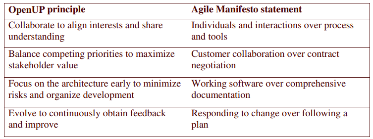
OpenUP principles
Table 1 – Mapping between OpenUP principles and Agile Manifesto
How OpenUP is organized
Content Areas
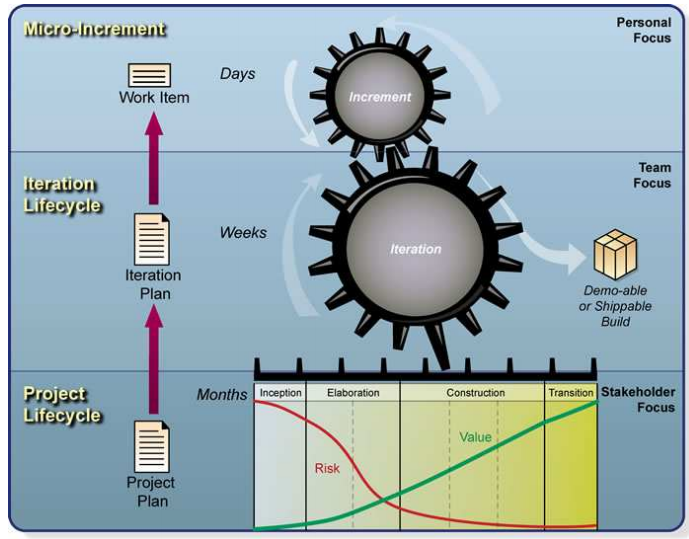
The OpenUP content addresses organization of work at personal, team and stakeholder levels, as seen in Figure 1.
Figure 1 – Organization of work and content focus in OpenUP
Roles
The essential skills needed by small and co-located teams are represented by OpenUP roles:
Stakeholder represents interest groups whose needs must be satisfied by the project. It is a role that may be played by anyone who is (or potentially will be) materially affected by the outcome of the project
Analyst represents customer and end-user concerns by gathering input from stakeholders to understand the problem to be solved and by capturing and setting priorities for requirements.
Architect is responsible for designing the software architecture, which includes making the key technical decisions that constrain the overall design and implementation of the project.
Developer is responsible for developing a part of the system, including designing it to fit into the architecture, and then implementing, unit-testing, and integrating the components that are part of the solution.
Tester is responsible for the core activities of the test effort, such as identifying, defining, implementing, and conducting the necessary tests, as well as logging the outcomes of the testing and analyzing the results.
Project Manager leads the planning of the project in collaboration with stakeholders and team, coordinates interactions with the stakeholders, and keeps the project team focused on meeting the project objectives.
Any Role represents anyone on the team that can perform general tasks.
Disciplines
The OpenUP method content is focused on the following disciplines:
Requirements,
Architecture,
Development,
Test,
Project Management,
and Configuration & Change Management.
Other disciplines and areas of concern were omitted, such as Business Modeling, Environment, advanced Requirements Management and Configuration Management tools setup. These concerns are either considered unnecessary for a small project or are handled by other areas of the organization, outside the project team.
Process Phase and Process
OpenUP applies the Unified Process phases:
Inception,
Elaboration,
Construction,
and Transition.
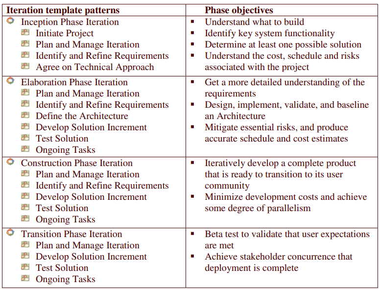
When taken together, these basic building blocks are also used to address the objectives for each phase (see Table 2 for a mapping between patterns and phases objectives).
Table 2 – mapping between patterns and phases objectives
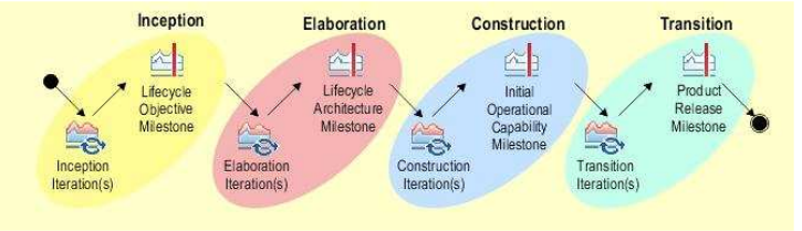
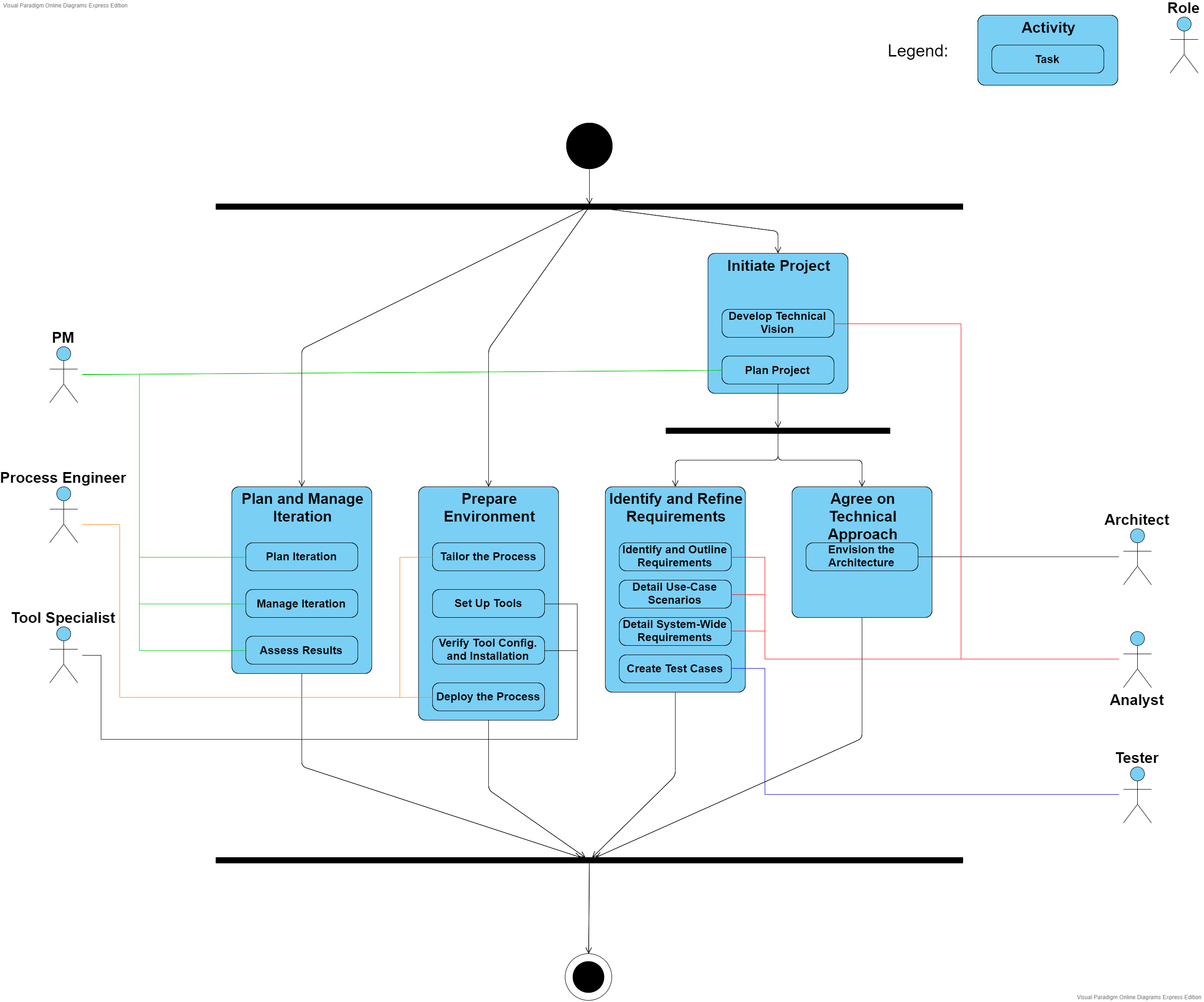
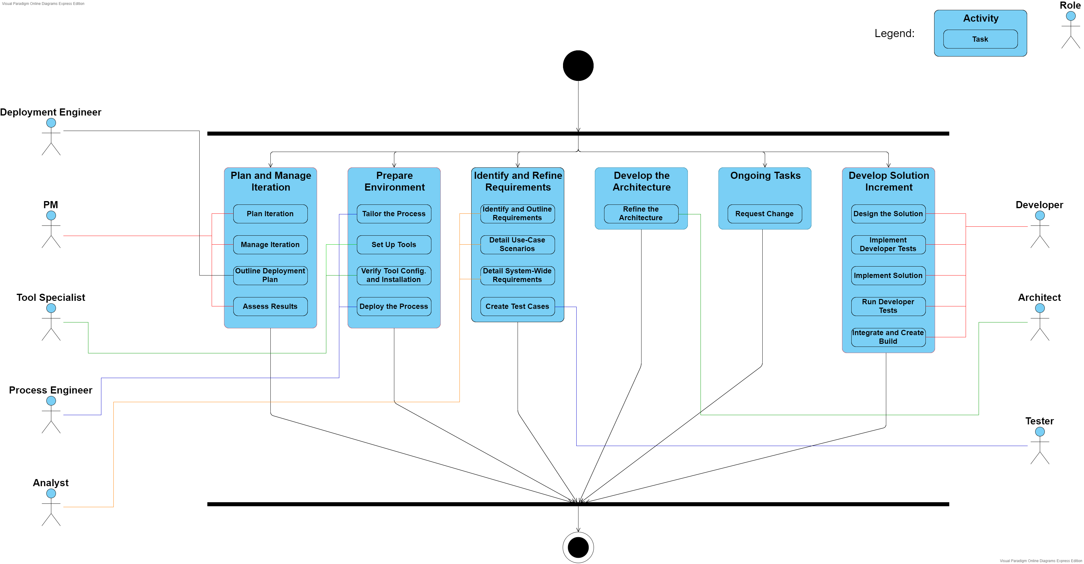
When we sequence the iteration template patterns (occurring as many times as needed), we have a delivery process – a complete and integrated approach for performing a specific project type (as seen in Figure 3). A delivery process describes a complete project lifecycle and is used as a reference for running similar projects.
Figure 2 – OpenUP delivery process
Reusable method content is created separately from its application in processes. Method content provides step-by-step explanations, describing how specific development goals are achieved independent of the placement of method elements within a development lifecycle.
Processes take these method elements and relate them into semi-ordered sequences that are customized to specific types of projects. Method elements are organized into reusable pieces of process called capability patterns, providing a consistent development approach to common project needs. These patterns are made from organizing tasks (from the method content) into activities, grouping them in a sequence that makes sense for the particular area where that pattern is applied.
Patterns can be small and focused in particular areas like iteration management, project initiation, architecture definition and so on. These are considered the basic building blocks to create larger patterns or delivery processes (defined below).
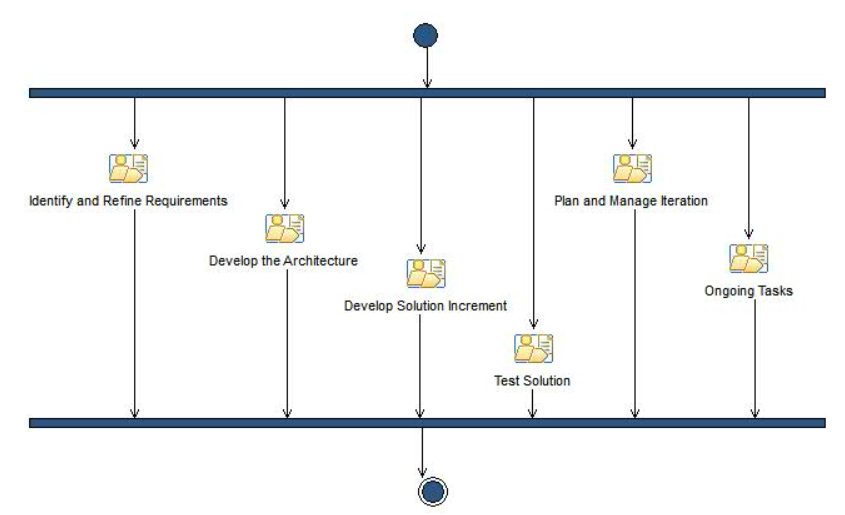
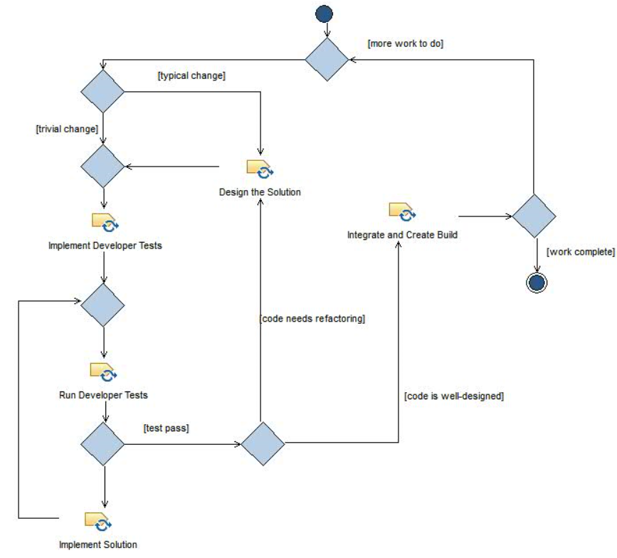
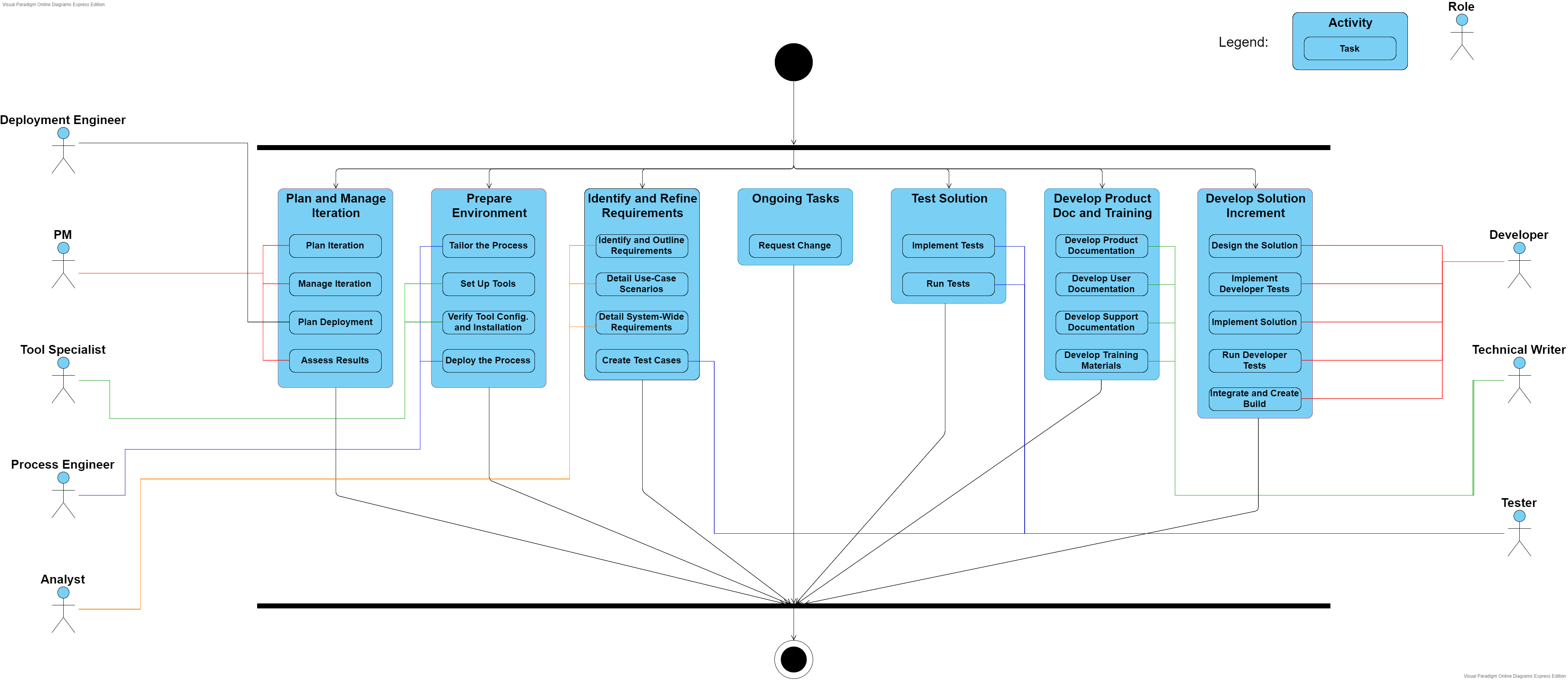
One example of basic building block in OpenUP is Develop Solution Increment pattern, as depicted in Figure 4.
This activity provides a way to perform goal-based planning and execution of work. Work is taken on by developers, and work progress is tracked based on the goals achieved using the designed, developer-tested, and integrated source code.
Figure 3 – There are activities in the workflow of Elaboration phase includes the "Develop Solution Increment"
Figure 4 – The "Develop Solution Increment" activity
Tasks
A task is unit of work a role may be asked to perform. In OpenUP, there are 18 tasks that the roles perform either as primary performers (the responsible for executing the task) or additional performers (supporting and providing information used in the task execution).
The collaborative nature of OpenUP is manifested by having the primary performers work with a range of other individuals when performing a task.
Artifacts
An artifact is something that is produced, modified, or used by a task. Roles are responsible for creating and updating artifacts. Artifacts are subject to version control throughout the project lifecycle.
Lesson 1.1: Create the UML project
In this lesson, you create a new UML project and become familiar with the use-case model template.
Lesson 1.2: Identify the use cases
In this lesson, you identify the significant use cases in the PiggyBank online banking system. The use cases describe the functional tasks that the PiggyBank application performs.
Lesson 1.3: Identify actors
In this lesson, you identify the actors of the system. The Account Operations use-case diagram identifies the key actors and the roles that they perform in the system. You must identify all the actors before you can create the diagram.
Lesson 1.4: Create the Account Operations use-case diagram
In this lesson, you create the Account Operations use-case diagram by modeling the relationships between the actors of the system and the use cases.
Lesson 1.5: Create the Display Balance activity diagram
In this lesson, you create the Display Balance activity diagram, which shows the events that occur when a customer or teller requests to display the balance of a bank account.
Lesson 1.6: Create the Transfer Money activity diagram
In this lesson, you create the Transfer Money activity diagram.
Lesson 1.7: Create the Cash Check activity diagram
In this lesson, you create the Cash Check activity diagram.
Lesson 2.1: Create a new PiggyBank analysis model
In this lesson, you create a new analysis model by using the built-in analysis-model template. The analysis-model template provides an example of a properly structured analysis model that you can use to quickly create your own analysis model by using the existing Rational Unified Process® (RUP) stereotypes and template diagrams.
Lesson 2.2: Identify the PiggyBank classes
In this lesson, you identify the main objects that comprise the PiggyBank online banking system. You can describe these objects as classes, because UML classes provide a convenient template for describing the attributes and relationships of an object. You can discover the main PiggyBank objects by analyzing the project-requirements documentation and highlighting all the nouns. You can group the common nouns into a list, and then identify them as an entity, controller, or boundary type class. These classes create the domain diagrams, which then form the foundation for the design model.
Lesson 2.3: Create the PiggyBank domain-model diagram
In this lesson, you create the Account Operations functional area and the PiggyBank domain-model diagram. The domain-model diagram describes the domain of the PiggyBank system by using a class diagram that shows the main classes in the system.
Lesson 2.4: Create the Account Operations use-case-realization overview diagram
In this lesson, you create the Account Operations use-case-realization overview diagram. You realize the Display Balance, Transfer Money, and Cash Check use cases by creating a dynamic and static view of the information in each use case.
Lesson 2.5: Create the Display Balance Participants diagram
In this lesson, you create the Display Balance Participants diagram. The Display Balance Participants diagram models the static structure of the Display Balance use case.
Lesson 2.6: Create the Display Balance sequence diagram
In this lesson, you create the Display Balance sequence diagram. The Display Balance sequence diagram shows the workflow of the functional task.
Lesson 2.7: Create the Transfer Money Participants diagram
In this lesson, you create the Transfer Money Participants diagram. The Transfer Money Participants diagram models the static structure of the Transfer Money use case.
Lesson 2.9: Create the Cash Check Participants diagram
In this lesson, you create the Cash Check Participants diagram. The Cash Check Participants diagram models the static structure of the Cash Check use case.
Lesson 2.10: Create the Cash Check sequence diagram
In this lesson, you create the Cash Check sequence diagram. The Cash Check sequence diagram shows the workflow of the Cash Check functional task.
Lesson 2.11: Document the analysis classes of the PiggyBank online banking system
In this lesson, you complete the PiggyBank domain model by documenting the main classes in the PiggyBank online banking system. You document the key abstraction, key control, and main user- interface classes by creating diagrams that use the existing account-operations analysis elements.
Lesson 3.1: Create a new design model
This lesson creates a new design model by using the built-in Enterprise IT Design Model template.
Lesson 3.2: Identify the implementation design subpackages and create the PiggyBank package diagram
In this lesson, you create the PiggyBank package diagram that describes the relationships between the packages in the PiggyBank online banking system. The PiggyBank package diagram is an overview diagram that helps you to design your application around a proposed architecture. You also identify and create the implementation design packages that make up the model.
Lesson 3.3: Create the CityBank integration design layer
In this lesson, you create the Citybank integration design layer. This layer describes the integration between the external CityBank system that verifies PiggyBank banking transactions and the PiggyBank system. The integration design layer is part of the realization of the Cash Check use case.
Lesson 3.4: Create the package structure of the business design layer
In this lesson, you create the package structure and package diagram of the itso.ad.business design layer. The itso.ad.business layer contains the business logic of the PiggyBank design model. The itso.ad.business layer contains the implementation design subpackages called delegate.ejb, ejb, and framework.
Lesson 3.5: Create the framework component layer
In this lesson, you model the framework layer of the itso.ad.business package. The framework component layer separates the client interface from both the persistent application data and the implementation of the application. The framework component layer contains the transfer object and delegate interfaces, as well as the delegate factory classes and exceptions.
Lesson 3.6: Create the EJB component subpackage
In this lesson, you model the EJB implementation-design subpackage. This subpackage models the Enterprise JavaBeans (EJB) layer that contains the domain models that persist the data for the application. The EJB layer implements the business logic for the itso.ad.business layer.
Lesson 3.7: Create the EJB delegate component subpackage
In this lesson, you model the delegate.ejb subpackage.
Lesson 3.8: Apply a profile to the design model
In this lesson, you apply a profile to the design model and you apply stereotypes to UML classes.